Troubleshooting Addressable Ins and Outs
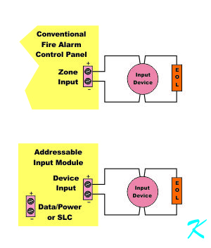
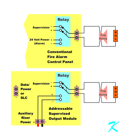
An input circuit on an addressable input circuit is exactly like a zone input (Initiating Device Circuit or IDC) on a conventional panel, an output circuit on an addressable supervised output module is exactly like a Notification Appliance Circuit (NAC) on a panel.
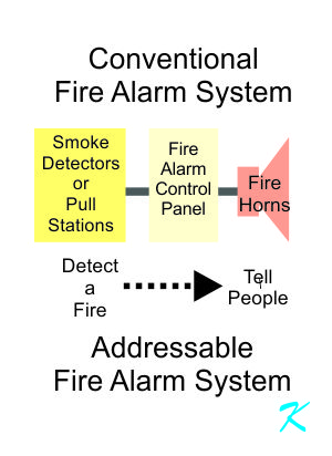
The purpose of an addressable fire alarm system is the same as a conventional fire alarm system
By Douglas Krantz
Anyone troubleshooting a system, like a fire alarm system, has to be able to look at the system being serviced from many different directions.
An example is the Initiating Device Circuit (IDC). The IDC has four different functions; it has to be looked at from four different directions to understand the circuit.
A
fire alarm system's main purpose is to detect fire and then tell people about the fire. A conventional fire alarm system does this detection-telling, and so does an addressable fire alarm system.
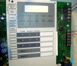
Besides a better display on the addressable fire alarm system and the extension of the Central Processing Unit's control bus (the
Signaling Line Circuit or SLC), also referred to as a data/power bus), the bottom line difference between a conventional and an addressable fire alarm system is location of the zone inputs and outputs for the Fire Alarm Control Panel (FACP).
An Addressable Device Input or Output is a Conventional Zone Input or Output
In a fire alarm system, both electrically and functionally, there is no difference between a
conventional input or output zone and an addressable input or output zone.
When troubleshooting, knowing that the circuit status can be checked right where one is at saves a lot of time running to the control panel. Basically, by using a voltmeter, the same exact troubleshooting techniques can be used on the addressable module's device wires as are used on the conventional panel's zone input or output.
Conventional Panel Input Zone
On the circuit board of a conventional FACP (Fire Alarm Control Panel), the zone inputs and outputs are screw terminals; the zone wires to the devices are wired directly onto the main circuit board itself. The communication path for the zone inputs or outputs on a conventional fire alarm system (defined by the NFPA) is usually Class B or Class A.
Addressable Input or Supervised Output Module
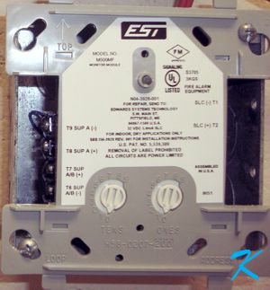
The zone inputs and outputs on an addressable fire alarm panel are not on the main circuit board, they're on modules that use a data/power bus (usually a Signaling Line Circuit or SLC) to communicate with the main CPU (Central Processing Unit) of the fire alarm system. Basically, the zone wires to the devices are directly connected to input or output modules.
The communication path for the input or output devices on an addressable fire alarm system is usually Class B or Class A (defined by the NFPA) on the device side of the module. Even between a smoke detector head and its addressable base, the communication path could be considered Class B because removing the smoke head from the base will produce a trouble on the panel.
The communication path between the module and the panel, however, can be
Class A, Class B, Class N, or Class X.
The Device Side of an Addressable Module is Conventional
To troubleshoot properly, one has to understand just what is being worked on.
A conventional panel has zone inputs from the detection devices like pull stations and waterflow switches, and zone outputs to the notification appliance devices like horns and strobes.
The same with an addressable system. An Addressable Input Module has an input from the detection devices like a pull station and a waterflow switch, and an Addressable Supervised Output Module has a device output to the notification appliance devices like horns and strobes.
Both conventional zones and addressable module device connections can be used with many if the exact same devices.
Input Zone and Input Module
Conventional input and output zone terminals on the panel supervise the wiring to the devices using a continuity check of the wiring.
The same with an addressable system. Addressable input and output modules supervise the wiring to the devices using a continuity check of the wiring. Trouble detection methods on the conventional and addressable systems are the same.
When an input device like a pull station shorts the zone drawing more current because it's in alarm, a conventional input zone detects an alarm.
The same with an addressable system. When an input device like a pull station shorts the zone drawing more current because it's in alarm, an addressable input module detects an alarm. Alarm detection methods on the conventional and addressable systems are the same.
Output Zone and Output Module
A conventional Notification Appliance Circuit output zone (NAC) sends alarm power to the devices when its internal
relay changes state from supervision to alarm.
The same with an addressable system. An addressable supervised output module sends alarm power to the devices when its internal relay changes state from supervision to alarm. NAC voltage reversal in alarm is the same for the conventional and the addressable systems.
In order to protect the panel's power supply, a short on a conventional NAC zone output won't allow the control panel's NAC relay to apply power to the zone. The same with an addressable system.
The same with an addressable system. In order to protect the riser's power supply, a short on an addressable supervised output module's device output won't allow the module's NAC relay to apply power to the zone. Short protection is the conventional NAC circuit and the addressable NAC circuit.
Addressable Zones are Conventional Zones
The words used to describe the connections may be different, but just like the zone terminals of the conventional fire alarm panel, the device terminals on an addressable module are really zone terminals.
When Troubleshooting, Use the Voltmeter
When a conventional fire alarm system is in alarm or trouble and you can't figure out why, you look at the voltage on the zone input or output of the conventional panel.
- If the voltage is too high, a wire is probably broken somewhere or a terminal has come loose
- If the voltage is too low, a device may be in alarm or there is a soft or hard wire-to-wire short
- If the voltage is reversed, the system may be in alarm
There are other rarer possibilities, but measuring the voltage is a good test to start with.
Example
Using this technique, many times I have stood in the sprinkler riser room while the sprinkler fitter was adjusting the low air pressure switch. By placing the voltmeter on the
input terminals of the module used to monitor the low air pressure switch, and watching for the voltage to suddenly drop to zero, I could tell the sprinkler fitter exactly when the low air switch was set right. When the pressure switch returns to normal (the proper amount of air pressure in the dry sprinkler system) I read a normal supervision voltage on the input terminals to the module.
Measuring voltage using this method saves a lot of time running to the fire alarm control panel in another part of the building just to check status.
