A
fire alarm system is in a building to detect fire and warn people of the fire. Many parts of a fire alarm system are installed to make sure that the detection and warning system works at all times.
Trouble on the panel is one method the fire alarm system has to make sure the system, when it breaks, can be fixed on a timely basis.
Troubleshooting
As a troubleshooter, the first thing a technician does when arriving at the building site to find problems is to look at the
Fire Alarm Control Panel (FACP) to see what it says about the troubles. The FACP and its display, however, is not the most important tool that a technician works with.
Voltmeter
By far, the most important tool that a technician uses to find problems in a fire alarm system is the voltmeter.
The display on the FACP can only tell you that there is a problem with a device in the field, the voltmeter can tell you what the problem is; the display on the panel can only tell you that there is trouble with a specific smoke detector, the voltmeter can tell you if the smoke detector is receiving power and signal.
Cheap Voltmeter
One thing that most fire alarm technicians don't understand is that that a cheap digital voltmeter is better than an expensive digital voltmeter. This, I have to explain.
The voltages on any fire alarm system are not precise, even power supply voltages can normally be between 20 volts and 27 volts. An expensive digital voltmeter can only show you that the voltage is on a circuit, approximately what the voltage is, and whether the voltage is steady; a cheap digital voltmeter can show that same voltage is on the circuit, whether the same voltage is steady, and provide the same reading of the same approximate voltage as the expensive one.
The difference between the two meters is that the expensive voltmeter is too big and too expensive to be ALWAYS carried while troubleshooting in a building; the cheap voltmeter is small enough to ALWAYS keep in a pocket or on the belt (so it is ready to be used anywhere and at any time) and it is also inexpensive enough to be replaced if it is lost or stolen.
Bottom line for you as a troubleshooter, a cheap voltmeter is better because it can always be carried with you and be always ready to be used.
Class A (Addressable) Fire Alarm Loop
The Signaling Line Circuit (SLC), which is what a Style type fire alarm loop is, carries power from the fire alarm panel to the detectors and modules in the field, and carries signals from the detectors and modules back to the control panel.
The power on the circuit, depending on the manufacturer of the panel, could be anywhere from 16 volts to 24 volts, but that is NOT what the voltmeter is going to show you. Because there is data riding on the circuit along with the power, the voltmeter is going to show you a very unsteady 10 volts to 24 volts, always changing from the low voltage to the high voltage and back every half second or so.
This changing voltage on the SLC (Signaling Line Circuit) is normal and it is what should be seen on the circuit. Get out your voltmeter and measure it, get used to reading the voltage. That is how you can see the problems you have to troubleshoot.
Class B versus Class A
Class B (Addressable) carries the power and signal to and from the detectors. The Class B circuit is connected to the control panel at only one end of the circuit. If a wire is disconnected from a smoke detector in the middle of the loop, all devices on one side of the connection are going to lose power and signal. There is no extra (redundant) path for the power and signal to reach the devices beyond the wire break.
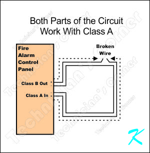
Class A (Addressable) also carries power and signal to and from the detectors. The Class A circuit, however, is connected to the panel at both ends of the circuit. If a wire is disconnected from a smoke detector in the middle of the loop, all devices still receive power and signal because, at one end of the circuit or the other, they are all still connected to the control panel. There is an extra or redundant path for the power and signal to reach the devices on both sides of the wire break.
Use Your Voltmeter
Don't take my word for it. You need to get used to carrying and using your voltmeter.
Stand at the fire alarm control panel and read the voltages on the SLC (Signaling Line Circuit). The voltages you read will be varying up and down, but the voltages will be there.
Now go to the place you disconnected a wire, but don't disconnect the wire. The first thing to do is to confirm that you are reading the same voltage (on the SLC) at the device as you were reading at the panel.
Once you have read the voltage to confirm what is normally getting to the device you are looking at, disconnect one positive wire from the device.
Now use your voltmeter again. Check the voltage on the disconnected positive wire (measure the voltage between the disconnected positive wire and the negative wire). This should be approximately the same voltage as you were getting on a normal circuit.
Without reconnecting the wire, use your voltmeter again. Check the voltage on the other positive wire (measure the voltage between it and the negative wire). This should still be approximately the same as the voltage you were getting on a normal circuit.
No Device Trouble
Because all the devices are still connected to the fire alarm control panel and still communicating with the control panel, none of the devices are shown as being in trouble. Remember that the troubles on the panel aren't really to make sure the wires are good, the wires don't detect fire or warn people of fire; the troubles on the panel are to show that there is a problem with the devices that detect fire and warn people.
Even though you have disconnected a wire, all of the devices are still connected to the panel, and all the devices work to detect fire or warn people of the fire. Because all of the devices are working normally, the panel is not going to show that there is a trouble with the devices.
The panel does, however, show that there is a problem with the wires, it shows a Class A or Style 6 Loop trouble. To fix the Class A or Style 6 Loop trouble, just put the wire back on the device and reset the panel.
Douglas Krantz