Can There be Too Many T-Taps on an SLC?
On a Signaling Line Circuit, Signal Pathways and Electrical Wiring are different concepts. Class A systems cannot have the Pathway T-tapped, but Class B systems can have their pathways T-tapped. Electrically, though, all devices on an SLC are T-tapped; electrically, all devices are effectively home run.
By Douglas Krantz
There are two ways of looking at T-taps: Signal Path and Electrical Wiring.
Signal Path
When looking at signal path, you're look at "a pair of wires that together,
carrying a signal or some power".
The signal path is what the National Fire Protection Association (NFPA) is looking at when discussing the
Classification of Circuits (Class A, Class B, Class C, Etc.).
For Class A pathways, every device is along a
single pathway. The pathway starts at the panel and ends at the panel. No matter where the path leads through a building, the start and end of the path is inside the panel in case there's a problem; the panel can use either end of the pathway to communicate with the devices.
For
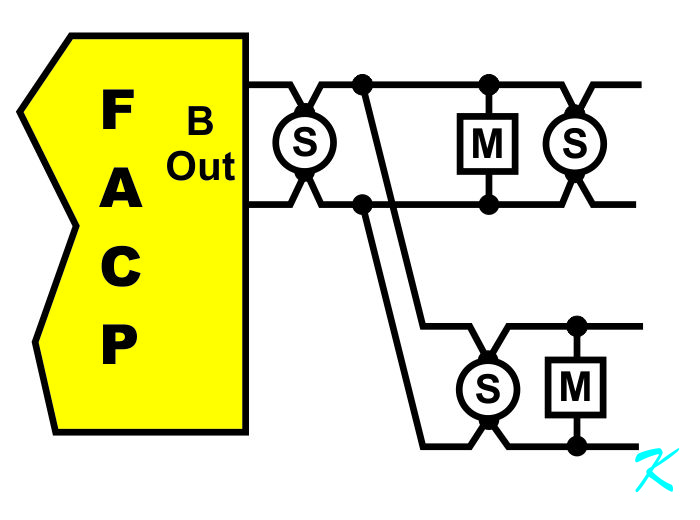
Class B (Signaling Line Circuit or SLC), every device is still attached to the pathway. A Class B SLC, however, only starts at the panel. A Class B SLC can be a single pathway, or have as many T-taps in the pathway as necessary.
Terminating Resistor
In process automation systems, large amounts of data are sent back and forth in a short period of time. This makes for "Large Bandwidth". For fire alarm systems, at least when compared to process automation, small amounts of data are sent back and forth is a long period of time, this makes for "Small Bandwidth". This bandwidth issue is critical when considering what should be done with the ends of wires.
The signal path is what electronic technicians and engineers look at when considering wave length of signal transmission. Related to that is the speed of travel for the power or signal along a pair of wires (usually somewhere around 2/3 the speed of light), and conversely, how far the power or signal travels along the pair of wires in a given length of time.
Keep in mind that energy (sometimes referred to as power) cannot be created or destroyed, it can only be converted.
For a small bandwidth fire alarm system, the data-rate (baud-rate or number of bits-per-second) is so slow compared to the length of wire that when there's a data-bit change from a zero to one or a one to zero, the power of the signal has time to hit the end of the wire pair, and even bounce back and forth from one end of the circuit several times before the next data-bit change can occur. In other words, the power reflected from the end of the circuit does not interfere with the original signal because the original signal is so dreadfully slow.
On the other hand, for a large bandwidth RS485 circuit used in automation, the data-rate is high enough that by the time the power of a signal has reached the end of the wire, the original signal could easily have changed from one to zero and back several times.
The reflected signal has not gone away. As it returns from the end of the wire pair, it will interfere with the new original data, and the receiving equipment will be confused by the double, triple, or more sets of data. That is why there's a resistor at both ends of the wire pair in an RS485 circuit: to soak up the power of the signal so it doesn't bounce back, or get reflected, from the end of the wire pair.
The resistor may be at the end of the circuit, but to differentiate this resistor from the fire alarm system's
End of Line Resistor, the technical term for this resistor is "Terminating Resistor". It terminates the wire pair.
In broadcasting or radio communications, the terminating resistor is also known as a "Dummy Load". These are bigger wattage value resistors than the ones used with RS485 circuits, but they do the exact same thing, they soak up the power of the signal so it doesn't bounce back. (In case you're wondering, I've worked with a 50-Ohm, 35,000-Watt Dummy Load [Terminating Resistor].)
Years ago, in Duluth Minnesota, someone unbolted an FM radio antenna from the top end of the transmission cable going up the tower. This caused the power of the signal to bounce back (get Reflected). The transmitter bounced that power back up the tower, along with added new power. The power kept bouncing up and down the tower - with new power added each time. In not too long, the top third of the tower became a torch, at least for several minutes. Quite a few people saw it burn. There's a lot of power from an FM radio transmitter. The cable going up the tower had better be terminated with an antenna, or the cable will start burning with the heat from the power as it keeps bouncing up and down the tower.
Electrical
In a conventional or addressable fire alarm circuit, for all practical purposes, the copper of the positive wire is continuous. No matter how many devices are connected, electrically the positive wire is a single piece of copper. The same with the negative wire, no matter how many devices are connected, the negative wire is still a single piece of copper.
OK, on an addressable EST Signaling Line Circuit (SLC), EST adds a small value resistor at each device location (less than an ohm or two). For electrical purposes, though, even the negative wire on an EST system can be considered to be a single piece of copper.
In essence, all devices in a fire alarm system are T-tapped off of the positive and negative wires. Electrically, the fire alarm control panel can't tell if the devices are home run, in a Class B circuit, or in a Class A circuit.
However, to make sure the devices are connected to the panel (supervise the devices) on a Signaling Line Circuit (SLC), the control panel continually takes attendance (polls the devices) to make sure they stay connected. It does this with the data that it sends and receives from the SLC. That's why, with Class B SLCs, T-taps are allowed; no one cares if the wires work (wireless fire alarm systems don't have wires), they only care that the devices stay connected to the panel.
End of Line Resistor
Conventional fire alarm circuits use end of line resistors. The end of line resistor in a conventional fire alarm circuit does not function to soak up the power of a signal; the end of line resistor is a "circuit completer".
A conventional fire alarm system supervises the wires of the Class A or Class B circuit. To supervise the wires, a conventional fire alarm system performs a continuity check on the wires.
To perform the continuity check, the panel runs a small electrical current through one of the wires - all the way to the end. The current goes through the end of line resistor, and returns to the panel on the other wire.
This is how the control panel knows when device is disconnected; when a device is disconnected, the wires to the device have to be disconnected. By disconnecting the wires for a device, the continuity path is interrupted, and the panel displays a trouble with the system.
Number of T-Taps
I have fixed hundreds of buildings with Signaling Line Circuits, some with T-taps and some without T-taps. One thing I have noticed with all of these buildings is that there are no two buildings wired the same way. Even when two buildings look identical on the outside, they are never wired the way on the inside. I have had to guess whether there are T-taps, and then guess to see where the T-taps are located.
I've never had electrical trouble because there are too many T-taps. The frequencies used with signal transmission are always so slow that T-tapping isn't a problem. Unless the manufacturer lists a problem with T-taps (like EST), T-taps aren't an electrical or interference problem.
As a technician trying to follow wires through a building, though, fixing a problem with the wiring can be made more difficult because of the number of T-Taps. If there aren't enough T-taps, sometimes trying to follow the wire past all of the devices can be irritating. If there are too many T-taps, sometimes trying to figure out which way to go can be irritating.
Sometimes, it's impossible to have the right number of T-taps. On one visit to a building, finding a fault in the wiring is hampered because there aren't enough T-taps, and the next visit to the same building, finding a fault in the wiring is hampered because there are too many T-taps. You can't win for losing.
Because all of the buildings are so different, I don't know if there can be a formula for the number of T-taps, except to say to run the circuits in a logical manner.
For inexperienced fire alarm system installers in smaller buildings, about the best formula that could be used is "One T-Tap Per Floor". For medium size buildings, the formula that could be used is "Two or Three T-Taps Per Floor". Any other instructions as to how many T-taps to install become too complicated.