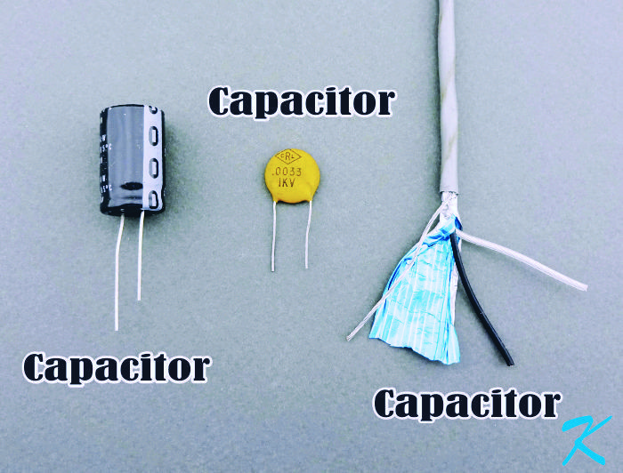
Capacitor
A capacitor is two conductors separated by an insulator.
That definition is pretty broad, but when looking at a capacitor this way, one can see that capacitance caused by unintended capacitors is everywhere.
Two Conductors
Normally, we think of a conductor as a copper wire, but conductors seem to be everywhere. You use a built-in conductor as a capacitor on a daily basis: your finger. Your finger is one conductor, and the other conductor is behind the glass screen of your cell phone.
A fire alarm circuit (SLC, IDC, NAC, any other two wire electronic or electrical pair of wires) has two conductors. When a shield is added around the two conductors, a third conductor has been added to the mix.
Conductors allow electrons to move from one place to another.
Insulator
The glass on the screen of your cell phone is an insulator; the insulation around each conductor in a circuit is an insulator; an air gap or vacuum gap is an insulator; ceramic material, paper, electrolyte, or other non-conducting material is an insulator.
Insulators keep electrons from moving from one place to another.
Electrons
Capacitance can be really thought of as the storage of extra electrons on one conductor, and electrons that have gone missing on the other conductor. Each electron, whether it's traveling or stuck on an atom, carries one voltage charge. The voltage charge is negative, and very small. Come to think of it, each proton also carries one voltage charge, the voltage charge on each proton is positive, and very small.
Look up
https://www.douglaskrantz.com/ElecElectricalFlow.html to get an idea of how electricity flows in a conductor.
Like charges repel each other; unlike charges attract each other. Capacitance is the negatively charged electrons on the surface of a conductor driving off the electrons on the surface of the other conductor, causing positive charges or "holes". Capacitance can also be thought of as positively charged atoms on the surface of a conductor pulling in the electrons to the surface of the other conductor. Electrons flowing on or off surfaces of conductors can be measured in electrical current, or amperes. This movement of electrons has to go on a conductor, around the insulator.
Applying voltage from the outside of the capacitor creates an imbalance in electrical forces that has to be countered by pulling electrons off one conductor and placing the electrons on the other conductor. There's an insulator in the way, so the electrons have to go around the insulator on another conductor. This is electrical current through the other conductor and is measured in amperage.
It takes more outside voltage to move more electrons on or off surfaces; it takes more outside voltage to create a greater imbalance. As the electrons move onto or off of the surface of the conductors, the resulting imbalance counters the outside voltage. This is another view of the stored voltage that is being referred to.
When the outside voltage is taken away, the capacitor's internal voltage tries to re-balance the charges again by moving the extra electrons on one conductor to the holes on the other conductor. Because there's an insulator between the conductors, the electrons have to go around the insulator using other conductors. This is measured in electrical current (amperage).
Total Capacitance
In a capacitor, several things affect the quantity of electrons / quantity of holes.
- As the conductors are moved closer together to each other, there can be more electrons / holes: the current is increased. Using wire that has thinner insulation on each conductor increases capacitance.
- As the conductors increase surface area, more electrons / holes can move: the current is increased. Increasing the length of the wire increases its surface area and increases capacitance, and increasing the diameter of the wire also increases its surface area and increases capacitance. Putting a shield (which is a conductor) around both wire conductors vastly increases the surface area, and vastly increases the capacitance.
- Different materials (dielectric) being used as insulators have different electrical force conduction: increased dielectric conduction means increased capacitance.
Capacitive Lag
In a perfect world, the voltage turned on at one end of a pair of conductors would show up at the far end just like it was turned on. That doesn't quite happen, however.
The rush of electrons coming into the wire pair reaches the other end, but only as some of the electrons / holes stay in the capacitance of the conductors. This means that the voltage seen at the far end starts building up right away, but takes longer to finally reach the full voltage than the original applied voltage.
This is a capacitive lag. Greater capacitance in the wire pair means greater lag time to change voltage.
When the digital signal being carried by the wires is high frequency (high baud rate), the lag can cut into the signal, preventing the receiver from understanding the transmitter.
Shielding - Gotta Have It
Shielding around a wire pair reduces electromagnetic interference. Sometimes, without the shielding, the outside interference received by the wires interferes with the intended signals.
If there is interference, consult with the equipment manufacturer to know if shielding can be used to reduce interference.
Shielding - Can't Have It
Shielding has a large surface area around the conductors; shielding vastly increases capacitance. Because of the huge increase in capacitance when shielded wire is used, the capacitive lag caused by using shielded wire can corrupt the intended signals. The shielding is an unintended capacitor.
Before using shielded wire, consult with the equipment manufacturer to know if shielding should be used.
Douglas Krantz