What is Capacitive Lag?
Capacitive lag is the lag in time needed to charge the capacitance between the wires. Capacitive lag isn't a time delay of the undistorted signal; it's a distortion of the data signal.
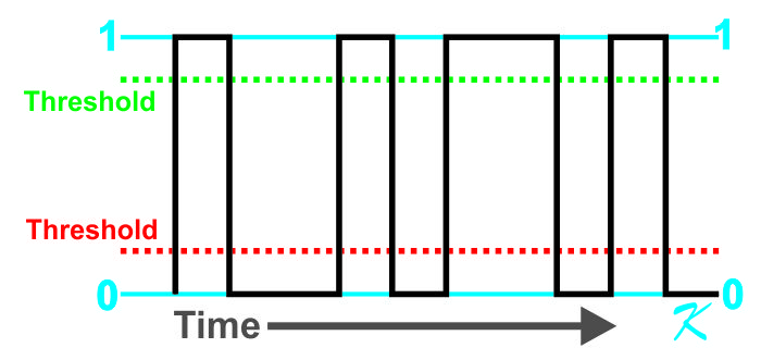
If there weren't any wire between the digital transmitter and the digital receiver, the signal would look like this. In order to read the transmitted signal properly, the receiver would not have a need for a threshold: a "1" would be properly received, and a "0" would be properly received.
By Douglas Krantz
One of the biggest issues that limit the length of wire used in a Signaling Line Circuit (SLC) is the amount of Capacitive Lag. If the wire length is too long, the capacitance of the wire will corrupt the data signals, and prevent proper communications between the panel and the devices.
At first glance, one would think that it's a distance-between-the-panel-and-the-module, but it's not. It's an issue of the total capacitance of the wire. T-tapped 10 times, or a single straight segment, it's the amount of wire, not the distance that matters.
Wire Capacitance and Signal Generator Resistance
A capacitor is defined as "Two Conductors Separated by an Insulator". Wire is a capacitor, wire also has resistance. And sending a signal through the wire, the power supply (digital transmitter or signal generator) has resistance.
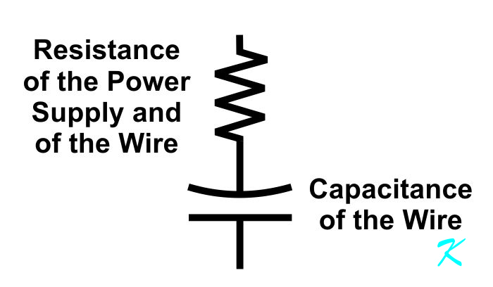
This means that the almost instantaneous voltage change that is sent by a digital transmitter takes time to charge or discharge the wires carrying a signal.
Threshold
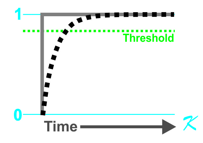
A capacitor takes time to change voltage because it takes time to put electricity into the capacitor, or time to take electricity out of the capacitor.
The time it takes for the voltage in the capacitor to cross a threshold, either charging or discharging, is the capacitive lag. Remember, the wires are a capacitor.
Why is there a threshold?
The threshold is less than the absolute "1" and greater than the absolute "0" voltage levels for three major reasons:
- There is always voltage loss on the circuit, so the voltage is going to be lower than what was sent
- There is always at least a little electrical noise injected on the data line as well as the ground-return line
- There is always at least a little capacitive lag on any data line
Most of these problems can be least mitigated by the data receiver. The data receiver stays at "0" until the voltage crosses the "1" threshold, and then the data receiver stays a "1" until the voltage crosses the "0" threshold.
Capacitive Lag Time Compared to Digital Bit Time
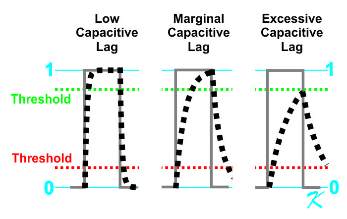
Compared to the digital signal being transmitted:
- Capacitive lag can be low so it won't really affect the signal between the digital transmitter and digital receiver. If the digital bit-time is long compared to the actual capacitive lag time in the wire, the capacitive lag is "Low".
- Capacitive lag can be marginal and possibly affect the signal between the digital transmitter and digital receiver. If the digital bit-time is shorter, or the actual capacitive lag time is greater, the capacitive lag is "Marginal".
- Capacitive lag can be excessive so the signal never crosses the "1" or"0" threshold, preventing any digital signal from being received. If the digital bit-time is too short, or the capacitive lag time is too long, no actual digital information is ever received.
Once the lag (as measured by the time it takes for the voltage to cross the threshold) exceeds a bit in time length, that's it. There is no more data. The data is now corrupted and may as well as not have been sent.
Capacitive Lag
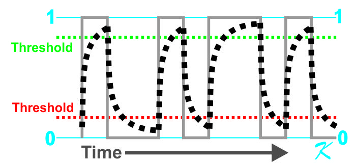
This lag in time, between when the data signal changes from a "1" to a "0", or a "0" to a "1", is always on the wires between the transmitter and receiver.
Compared to the data-bit length, though, if the lag is short enough, the data will be received correctly. If the lag is too long, some or all of the data-bits won't be received, and the data becomes corrupted.


