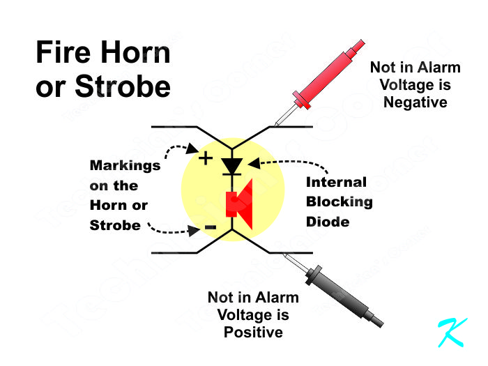
There are several possibilities, but one is very common, even for professional fire alarm installers; the horns or strobes may be installed with the incorrect polarity.
For many people, this is a problem because they used a voltmeter to check polarity on the wires. Then they connected the wire that measured
positive to the
"+" terminal on the horn or strobe and the wire that measured
negative to the
"-" terminal. Connecting the horns and strobes that way is wrong.
Now wait a second. Why is that wrong?
The problem is that when the wire polarity is being measured, the panel is not in alarm. The voltage on the wires at this time are for the panel's supervision of the wires.
The only time it's checking continuity (supervising the wires) is when the panel is not in alarm. That checking continuity is what the end-of-line resistor is for at the end of the circuit; it completes the circuit and allows the panel to check continuity through all of the wires.
When the panel goes into alarm, using an
internal relay the panel reverses the voltage. Then, when it's in alarm, the panel should be applying
positive voltage to the
"+" terminal, and
negative voltage to the
"-" terminal of the horn or strobe.
The reason for this voltage reversal is so the horn or strobe won't conduct current while the panel is not in alarm; when the panel is checking continuity. There's a diode inside the horn or strobe to prevent the current from going through.
It's only when the panel is in alarm that the wire marked
positive has
"+" voltage and the wire marked
negative has
"-" voltage. That's when electrical current should go through the horn or strobe so that it sounds off or flashes.
Bottom line, for a conventional NAC circuit, when the panel is not in alarm, connect the wire that has been measured
negative to the
"+" terminal and the wire that has been measured
positive to the
"-" terminal of the horn or strobe.
Of course, there could be other things causing the problem, but I would check voltage polarity on the horn or strobe, first.
Douglas Krantz