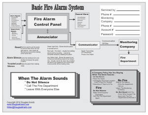
How do Pathways Affect Ground Faults?
With fire alarm systems, some pathways carry ground faults and some pathways don't carry ground faults. Ground faults that are carried by pathways have to show trouble on the panel.

By Douglas Krantz
Ground Faults are a big issue. Almost anytime there is a ground fault on a fire alarm system, the panel displays a trouble. Then, no matter what caused the trouble, the trouble has to be fixed. However, the NFPA has an exception to the rules regarding the displaying of ground fault troubles.
For all types of pathways for signal or power in building wide fire alarm systems, the rule of thumb for displaying a ground fault trouble goes something like this, "Whenever there is a ground fault, the panel will display a trouble."
There is an exception to this rule of thumb. "If the ground fault cannot affect anything else, under any circumstances, then the panel does not have to display a trouble when that particular ground fault occurs."
OK, the NFPA doesn't use these words, but that is the meaning.
Regarding any of the Classes of pathways (Class A, B, C, D, E, N, X), we as fire alarm designers, installers, and technicians have to know whether a signal pathway will allow a ground fault to affect the rest of the fire alarm system.
Multiple Paths Used
To get a signal from a device in the field to the control panel, or from the control panel to a device in the field, the signal sometimes travels down more than one path. Each path may be classified differently.
A waterflow switch, for instance, starts out on a conventional Class B path to send a signal to an addressable input zone module. The signal is processed in the zone module to make it addressable and then the addressed signal may be sent to the panel on a Class A Signaling Line Circuit (SLC) path.
To turn on the fire horns, the addressed signal is sent from the control panel to another addressable supervised output module on the Class A SLC path. Then the supervised output module sends the signal (power) to the horns using a conventional Class B path.
If there's more than one control panel in the fire alarm system, these same signals could be sent over Class N pathways, which may involve fiber optics as well as CAT(X) wiring.
As a signal travels from the detection device to the panel(s), and from the panel(s) to the fire horns
We have to be aware of all the types and Classes of pathways that a signal might travel through.
Direct Coupled and Indirect Coupled Pathway
When ground fault troubleshooting, a technician has to understand how various communication paths work in a fire alarm system. For this discussion, variations on how the paths transfer signals can be divided into two groups:
Direct Coupled and
Indirect Coupled.
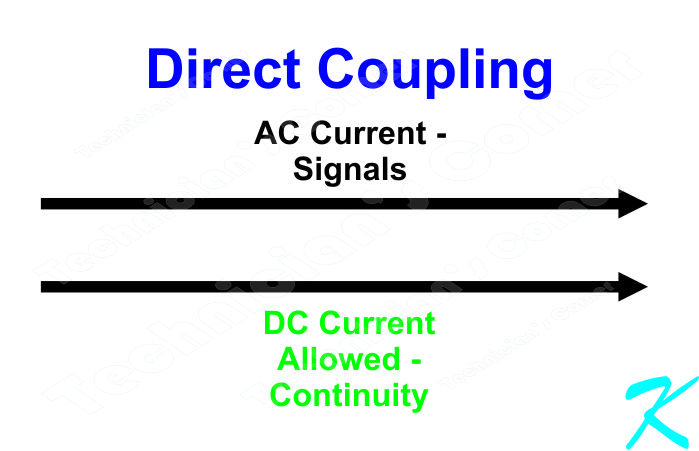 Direct Coupled
 is electrically connected or hard-wired - There are electrical current carrying copper wires used for transferring data between the electronics in all of the equipment and devices connected to the pathway.
Direct Coupled pathways would be:
- The Signaling Line Circuit (SLC)
- Security System Style Control and Power Loops (Four Wires - Plus, Minus, Send to Devices, Receive from Devices)
- RS485 circuit
- RS232 Circuit
- Power Circuit (like for door holders, detectors, control circuits)
- Any other pathway that use copper wires
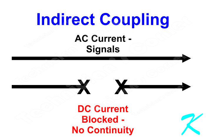 Indirect Coupled
 is not electrically connected or hard wired - There is no electrical connection between any of the electronic equipment or devices.
Indirect Coupled pathways would be:
- Radio Frequency (RF) Coupled like Wireless
- Magnetically Coupled (Transformer Coupled) like CAT(x)
- Optically Coupled like Fiber Optics
- Other non-electrical signal transfer system
Mixed Direct and Indirect Coupled is both a Direct Coupled pathway and an Indirect Coupled pathway wrapped up in the same physical outer jacket, like PoE (Power over Ethernet).
Mixed Direct and Indirect Coupled pathways have a direct hard-wired pair or pairs used to provide power to a device, and inside the same outer jacket, Magnetically Coupled (Transformer Coupled) pairs used to carry data between the device and the network.
Because they both the Direct and Indirect Coupled loops are in the same jacket, they could be considered to both be in the same pathway.
Continuity
The difference between Direct Coupled and Indirect Coupled is electrical continuity. It's not normally used in a fire alarm system, but a plain old light-bulb-and-battery continuity tester can often be used to check whether or not a pathway is Direct or Indirect Coupled.
No, don't do this, this is a mental test or a theory test of the pathway. Use an imaginary continuity checker because a real checker has a possibility of unforeseen damage. Connect your imaginary continuity checker to the positive wires at each end of the pathway, or connect your imaginary continuity checker to the negative wires at each end of the pathway.
If the data-path can turn on the light, the entire pathway is Direct Coupled, if the data-path can't turn on the light, the pathway is Indirect Coupled, at least at some point.
Ground Fault
One distinguishing factor between Direct and Indirect Coupling is whether a Ground Fault can affect the ability of the loop or pathway to transmit and receive data. In Direct Coupled systems, Ground Faults can affect the transfer of data, and often can affect the connected electronics. In Indirect Coupled systems, Ground Faults generally don't affect the transfer of data, or even the connected electronics.
If a ground fault does not affect data transmission or any of the connected electronics, the NFPA 72 uses logic in their rules and does not require the ground fault to show up as a trouble on the fire alarm system.
An example of the exemption would be a wireless detector. It sends it signals using Radio Frequency (RF) transmissions. There is no direct DC wired connection between the detector and anything else in the fire alarm system. If there is a ground fault on the detector, the ground fault could never cause a problem with any of the rest of the fire alarm system. A ground fault, in this case isn't a trouble, so a ground fault trouble doesn't have to be shown on the control panel.
A point of concern, though, is that this non-trouble requirement should be in writing in the approved maintenance manual for the system. Then again, if it's not in the manual, this non-trouble requirement might also be obtained (preferably in writing) through the technical support people for the fire alarm system manufacturer.