There are two systems that connect together, and they each have requirements: the beam detector and the fire alarm system.
Beam Detector
Usually, the OSI-90 Beam Detector comes as a conventional device, meaning that it uses relay contact closures to send a trouble and to send an alarm. When it is not in trouble or alarm, the connections for both the trouble and alarm relays are made to their common and open contacts on the beam detector. That way, if there is trouble, the contacts on the trouble relay will close.
In essence, the contacts short the alarm wires or the trouble wires together, allowing a large amount of current to flow.
The manual that comes with the beam detector has information showing how to connect it.
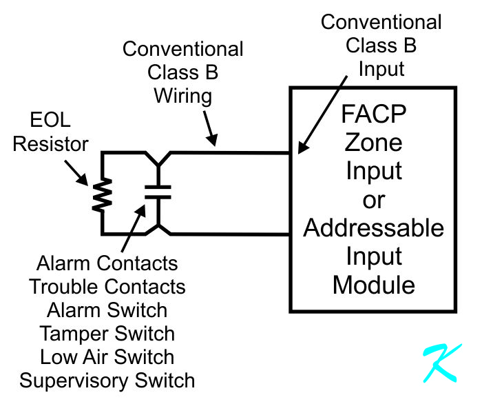
Fire Alarm System Input
The zone input on a conventional fire alarm system works exactly the same way that the input to an addressable input module; when the circuit starts to conduct a lot of current, the zone input or the addressable input module senses an alarm or a supervisory. A smoke detector draws some more current than normal from the input circuit, a closed switch or closed relay contacts draw a lot more current from the input. Drawing the extra current is how the input devices send their alarm or supervisory.
Because people's lives depend on the fire alarm system working, all input devices have to be connected to the panel at all times. An addressable device shows it's connected by responding to the panel when it's polled (the data equivalent of asking "Are You There?" and the data equivalent of "I'm OK!").
A conventional device, like a beam detector that has relay contacts, can't respond. Instead, the wires are supervised to make sure they're connected. The panel checks the wires by passing a small amount of current through all the wires, and also through all the screw terminals. If the electrical current stops, the panel concludes that the wire is broken, or a screw terminal has come loose, and the panel shows a trouble.
When the panel shows a trouble, the owner of the building calls for service.
End of Line Resistor
The whole purpose of the end of line resistor is to complete the circuit at the end of the line. That way, to make sure no wire is broken or come loose from a screw terminal, the electrical current is forced to flow through every wire, and every screw terminal.
If the end of line resistor is placed anywhere besides the end of the circuit, some wires and terminals will not be supervised with the electrical current. If a non-supervised wire breaks or come loose from a non-supervised screw terminal, no alarm or supervisory signal will be passed to the panel.
The bottom line is that if the end of line resistor is installed anywhere other than the end of line, there is a possibility that the problem won't be detected until the beam detector is tested and fails, or there is a fire that the beam detector doesn't show, whichever comes first.
Always install the end of line resistor at the end of the line.
Installation Sheet
In the box that comes with the addressable input module, or in the installation manual for the fire alarm system is a diagram showing exactly how the input circuit should be wired. This diagram includes the location of the end of line resistor. Following that diagram is the only proper way to wire the circuit.
Don't just throw away the installation sheet, it has lots of important information.
Douglas Krantz