Douglas Krantz - Technical Writer - Describing How It Works

What's the Purpose of the Zener Diodes?

When the switch contacts on any device close, the Zener diode pulls the voltage on the circuit down part way. If more than one switch contact is closed, because the Zener diodes are in parallel, the voltage is not pulled any further.

Disable switches prevent things from happening. Here a disable switch closes to put a zener diode into the circuit, pulling down the sensing voltage to 3.9 volts.
Hi Douglas,

I was searching on the internet for an explanation on what's the purpose of the Zener diodes in following wiring circuit. This circuit disables an explosion valve (valve which closes when an explosion is detected).

Since I found a very good and understandable explanation on the difference between a end-of-line resistor and a terminating resistor I thought maybe you could also give me a clear explanation of the use of those Zener diodes.

Thank you, G V

We'll start out looking at what this circuit is connected to. Keep in mind that I'm guessing from the circuit, but the idea of what's happening in the circuit is still the same.

The circuit is just about the same as a Conventional Class B fire alarm circuit. The "control box" it's connected to looks like it has explosion detection devices also connected to it, and when explosion is detected, the control box closes a valve for people safety as well as property safety and protection.

  1. Under normal circumstances, the control box is watching for explosion.
  2. When a cover is opened for maintenance, or maybe during certain cycles in the processing, the Control Box won't close the valve; it is disabled.
  3. If the wires in the circuit become wire-to-wire shorted, like if a forklift pinches a conduit shorting the wires together, at the very least, the trouble light and buzzer are turned on. Possibly, the process is critical enough that the valve closes - just in case.
  4. If a wire breaks in this circuit, or a disable switch becomes disconnected, there's a light on the control box that turns on and a buzzer sounds, letting you know that something needs immediate attention (trouble on the circuit).

Basically, even though there are only two wires being used in the circuit coming in on plug #4, the control box is looking for four different conditions.

Signal Sensing in the Control Box

If there is nothing connected to the screw terminals on the control box at P4(?), the voltage becomes the full power supply voltage (12 volts or some other power supply voltage). Normally, though, the circuit is connected and current flows through the plus and minus wires of the circuit and the End-of-Line Device (820 ohm resistor). When the circuit is normal, the current does not flow through any Zener diode or disable contact.

Normal Circuit

The current flow through the wires and end-of-line device on the circuit, though, sends a "normal circuit" signal to the controller box. Because of the small amount of current flowing in the circuit, the voltage at the screw terminals is "pulled down" from that power supply voltage to (this is a guess) 8 volts. The controller box looks at the screw terminals of Plug 4, and seeing that the voltage is pulled down to 8 volts instead of an open circuit of 12 volts, the wires are good and all disable switches are connected.

Disable Signal

When any disable contact is closed allowing current to flow through a Zener diode, the Zener diode, being a voltage regulator of 3.9 volts, pulls the voltage between the wires down further down to 3.9 volts. Because the voltage at one end of each wire is the same as the voltage at the other end of the wire, the screw terminals at plug 4 are also 3.9 volts. The controller box sees this voltage and disables the explosion valve.

Shorted Trouble

Shorted wires on the disable circuit look to be very bad. A short anywhere on the circuit will be basically connecting the wires in the circuit together. Functionally, a short will pull down the voltage between the wires to zero, and this zero voltage will be on the screw terminals of plug 4. The controller box does something at this point, perhaps it closes the explosion valve, or just turns on a trouble light and buzzer.

Zener Diodes - Not Resistors

Electrically, if more than one disable switch is closed, multiple Zener diodes would be in parallel. It doesn't matter how many Zener diodes are in parallel, the voltage is always going to be pulled down to 3.9 volts.

On the other hand, if resistors were used in place of the Zener diodes, then if more than one disable switch is closed, multiple resistors would be in parallel. Their combined resistance of the resistors in parallel is lower than and single resistor. The combined resistors would pull the voltage lower than 3.9 volts, and the Control box might detect the lower voltage as a wire to wire short. That might reenable the explosion circuitry, causing unknown production damage.

Open Trouble on the Circuit

If a wire breaks or comes loose from a disable contact device, the normal current in the circuit stops, and the voltage at the screw terminals is no longer being pulled down to 8 volts. The controller box then turns on a trouble light and buzzer.

Four Signals

  • Normal - 8 volts(?) on the screw terminals
  • Disabled - 3.9 volts (Zener voltage) on the screw terminals
  • Open or Broken Wire - Power Supply voltage on the screw terminals
  • Shorted Wires - 0 volts on the screw terminals

Douglas Krantz
Disable switches prevent things from happening. Here, a closed disable switch shorts out the end of line resistor, causing the circuit to draw more current, and pulling down the sensing voltage to somewhere around 3.9 volts.

Further Question

Mr. Krantz

Thank you for this very understandable explanation. It's a great help for me.

Like you noticed, the circuit is indeed connected to a controller which has explosion detection (pressure sensor) and when and when explosion is detected, the controller closes a valve for people safety as well as machine safety and protection. The circuit I mentioned is the circuit which is connected to the "disable" contact. When the device is disabled the controller will not check for an explosion. This is typically used for maintenance on the devices connected to the controller (local disable) or to remote disable the explosion controller from a PLC (Programmable Logic Circuit or Programmable Logic Control).

I still have some questions. At the end of this email I send you an extract of the manual of the explosion controller. As you can see for the setup with just one contact there is no Zener diode needed. How is this possible?

Furthermore, can this circuit detect a wire break after the first contact when the first contact is closed?

Thank you, G V

Single Device

Sometimes, we have to look beyond what a device is labeled and look at what a device is and what it really does.

We still have the four conditions of the circuit as shown on the screw terminals of P4 on the control box.
  • Normal - 8 volts(?) on the screw terminals
  • Disabled - 3.9 volts (Zener voltage) on the screw terminals
  • Open or Broken Wire - Power Supply voltage on the screw terminals
  • Shorted Wires - 0 volts on the screw terminals


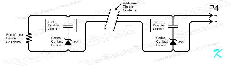
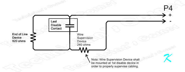
However, because of the exact location of the Wire Supervision Device (this is still a resistor), we have to mentally divide up the circuit between the wiring (shielded pair of wires) and the disable switch assembly (two resistors plus the Disable Contacts). All three components shown for the disable switch assembly have to be in the same box because any short condition to the left of the Wire Supervision Device (resistor) will be seen by the control box as a disable command rather than a short. (I'll explain further on down.)

Under normal circumstances, the contacts are open so no current flows through the switch. That leaves the End of Line Device (resistor) and the Wire Supervision Device (resistor) in series to pull the voltage down at the screw terminals of P4 of the control box. The total resistance of the End of Line Device (resistor of 820 ohms) and the Wire Supervision Device (resistor of 240 ohms) is 1060 ohms. That allows current to flow in the circuit (pulling the voltage at P4 down to around maybe 10 volts), showing the control box that the wires in the shielded pair of wires are complete and still connected at both ends.

Of course, a short in the twisted pair is still going to show up as a short to the control box because the voltage at P4 will still be pulled down to zero.

Now we get to the Wire Supervision Device. It does the exact same thing as the 3.9 volt Zener diode.

In the Single Disable Device circuit, the Disable Contact is wired across the End of Line Device (resistor). The 1st Disable Contact shorts out the End of Line Device (resistor) and allows a greater amount of current to flow through the Wire Supervision Device. The greater current pulls down the voltage at P4 to about what the 3.9 volt Zener diode pulls the voltage down to, sending the disable command to the Control Box.

The Control Box can't tell the difference between voltage pull downs by a Zener diode and voltage pull downs by a resistor. In either case, the signal sent is "greater electrical current" pulling down the voltage at P4 to about 3.9 volts. For all practical purposes, the resistor of the Supervision Device and the 3.9 volt Zener diode are the same device. Because of the exact wiring of the circuit, though, substituting one with the other may cause other problems.

Of course, the wire supervision resistor has to be mounted at the disable device so that an accidental wire to wire short in the wire will be seen by the Control Box as a short and not as a disable command.

There is no difference between the electrical contacts closing in the 1st Disable Contact and a wire-to-wire short to the left of the Wire Supervision Device. That means that the Wire Supervision Device (resistor) has to be installed at the Disable Contact rather than somewhere else in the circuit.

Multiple Device Wire Breaks

No electrical or electronic circuit is a catch-all for every circumstance. That's why someone should look at the control box both before and after maintenance.

Presumably, the Control Box is glanced at before any maintenance is performed. If there is trouble on the disable circuit, the trouble should be looked at before depending on the circuit to disable anything. Once the disable circuit is normal (without troubles), the disable circuit can be depended on while servicing the system.

If, while the 1st disable contact is closed, a wire breaks or comes loose further down in the circuit, the broken wire will not be detected by the Control Box.

Once the 1st disable contact is opened again and the open wire is still open, the Control Box will then show trouble. Just as a normal procedure, hopefully, the control box is at least glanced at once the maintenance is complete. The trouble will be seen and then the open wire will be fixed.

A wire-to-wire short, however, is going to be detected even when a disable contact is closed because the wire-to-wire short will short out all Zener diodes and the end of line device in the circuit.

Douglas Krantz


facpdoug@gmail.com
Index
Residential
Life Safety
Descriptions
Electronics
Maintenance
Suppression
This website uses cookies. See Privacy for details.
Fire Alarm Q&A Articles


No Charge - Unsubscribe Anytime


Make It Work Series of Books by Douglas Krantz
Free - Click and Download
Make It Work Series of Books by Douglas Krantz