Definitions:
DCS - Digital Control System
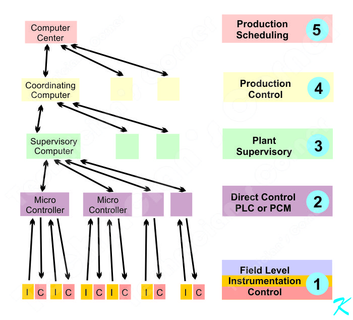
This is the overarching control system for the entire plant or refinery. This consists of a Computer Control System (the control system may consist of one computer or even a computer with sub-computers and sub-sub-computers), Direct Control Modules, and Field Level Devices.
The computers talk to each other and to the digital control modules over a network of short hard-wires, digital switches (routers), and fiber optic communication.
Often times the individual computers (Nodes) can become "Stand Alone" computers. If the main computer fails or the computer-to-computer data network fails, at least the subordinate computers will continue to operate, possibility shutting down the process on an emergency basis.
PLC - Programmable Logic Controller
These are devices that control the process according to a sequence of events that happen. When the proper events happen in the correct order, the PLC activates other actions.
Usually, the PLC is also controlled and monitored by a computer or computer network.
When the PLC is part of the Digital Control System, it can be used as the Digital Control Module. The Digital Control Module is the interface between the Field Devices, like hard-wired pressure switches or hard-wired motorized valves, and the computer Digital Control System.
The PLC has two basic functions:
- The PLC monitors inputs and controls outputs for a small interrelated section of a process.
Example: When a Field Device pressure switch senses the pressure has reached a certain level, it closes electrical contacts inside the switch housing. The closed contacts are a form of information, like a light switch on the wall, and this is sent to the PLC or the Digital Control Module.
The PLC then closes a relay inside it, sending electrical power to a control valve, shutting off the process material.
- The PLC sends information about what's happening into the computer network and also receives commands from the computer network.
Example: The PLC or Digital Control Module also send the information to the computer that controls this section of the process. Using this information, the Computer can also send information to the PLC or another PLC to shut a control valve.
If the PLC or Digital Control Module loses contact with its controlling computer, the PLC could be programmed to go into a "Fail Safe" or "Fail Secure" mode to either keep the process running, or to safely shut down the process.
P & ID - Piping and Instrumentation Diagram
Like an overall blueprint of a building, the Piping and Instrumentation Diagram (P & ID) is a block diagram; it's an overview of how the whole process system operates.
The P & ID is a block diagram showing the pipes being interconnected or the whole process being interconnected, along with the instrumentation (detectors and other inputs) and controllers (valves, actuators, motors, etc.).
The diagram shows what's important. It may show every mechanical device, every flange, every elbow, but it usually won't show the supports. It may show lines to indicate where electrical power or signals are sent, but it won't show every electrical conductor.
Answers to your questions:
- How are alarms hardwired to field equipment in a typical process plant like refinery, for example a high-pressure alarm monitoring pressure on a reactor or vessel?
The High-Pressure Alarm Monitoring is probably a pressure switch mounted on the side or top of the reactor. When the pressure inside the reactor reaches a certain level, the electrical contacts inside the switch change state, and using two wires to a Device Control Module (probably a PLC - level 2 on the block diagram).
The Direct Control Module (DCM) may be programmed to sound an alarm or shut valves or take other actions.
The DCM also sends a signal up the chain of computers to indicate what is going on. The computers at any level may be programmed to do things like sound alarms, shut valves, open valves, maybe start the Emergency Shut Down procedure, if no one takes other action. At this point, it's all in the programming.
Any action that is automatically taken would be programmed into the computer.
- How is the alarm hardwired such that the operator in the field as well as in the control room will be alerted?
The DCM also sends a signal up the chain of computers to indicate what is going on. The computers at any level may be programmed to do things like sound alarms, shut valves, open valves, maybe start the Emergency Shut Down procedure, if no one takes other action. At this point, it's all in the programming.
Any action that is automatically taken would be programmed into the computer.
- Can an alarm be a field device that is not accessible to the operator in the control room?
At this point, everything is connected to the computer network. The programming might not allow the operator in the control room to do something with a device, but that would be controlled by the programming, not the wiring.
For instance, the computer may not allow the operator to shut down something or start something because that could be a safety issue - overriding a safety valve might be a potential danger to people or property, so direct control by the operator in the control room might not be a good idea.
Douglas Krantz