A conventional Notification Appliance Circuit (NAC) has two normal conditions: Wire Supervision, when the horns aren't supposed to sound, and Alarm, when the horns are supposed to sound. The horns and strobes themselves are too dumb to show that they are connected, so the wires are supervised, not the horns and strobes.
NAC Wire Supervision
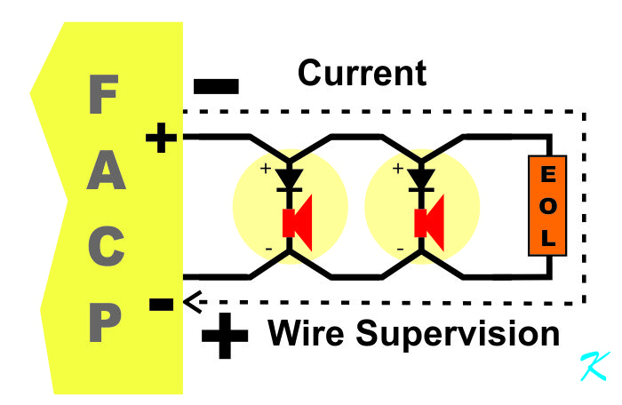
When the alarms are not sounding throughout the building, the wires are being supervised for integrity. In a conventional circuit, "Supervised for Integrity" is a long-winded way of saying, checked for continuity. If the continuity is broken, in other words a wire comes loose from a connection or a wire breaks, then the panel says there is trouble on the circuit.
During the time the circuit is being supervised, there is a reverse-logic problem. When the circuit is being checked for continuity, the horns and strobes cannot have current passing through them, so the voltage is reversed. When the circuit is being supervised, the blocking diode inside the horn or strobe is reversed biased, preventing current from passing through the device.
In other words, when the circuit is being supervised, the voltage polarity measured on the screw terminals on the panel is reversed from what is on the label.
(Watch out for things like labels on panels. One company I know of shows the polarity of the NAC connections differently from other companies. Read the Installation Manual carefully to make sure of the labels.)
NAC Alarm
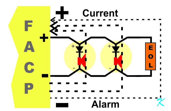
When sounding the alarm, the wires are providing power to the horns and strobes.
During the time the circuit is sounding the alarm, it is using forward-logic. Because the circuit is providing power to all the horns and strobes, the blocking diode inside the horns and strobes has to be forward biased, allowing current through them.
In other words, when the circuit is sounding the alarm, the voltage polarity measured on the screw terminals on the panel is correct on the label.
(Watch out for things like labels on panels. One company I know of shows the polarity of the NAC connections differently from other companies. Read the Installation Manual carefully to make sure of the labels.)
NAC Wiring
When installing a circuit for the first time, no one is using a voltmeter. The wiring diagram for the NAC power supply shows the exact wiring that should be used -
including the voltage polarity. In other words, the wiring diagram is meant to be blindly followed.
When using a voltmeter in the field to measure the voltage, keep in mind that the voltmeter measurements are being made while the NAC circuit is being supervised by the panel.
Because the circuit is being supervised, you have to use reverse logic. The wire that is measured as negative goes to the plus terminal of the horn or strobe, and the wire that is measured as positive goes to the minus terminal of the horn or strobe.
It's only when the panel is sounding the alarms that forward logic can be used. When sounding the alarm, the wire that is measured as negative goes to the minus terminal of the horn or strobe, and the wire that is measured as positive goes to the plus terminal of the horn or strobe.
Test All of the Horns and Strobes
Another word of caution. I know it sounds dumb, but the panel does not go into trouble when a horn or strobe is wired backward. That is another reason that the circuit has to be tested by sounding the alarm and walking around; to make sure everything is wired correctly.
A number of times, I have seen where an installer incorrectly wired the horns or strobes. Then when certifying, the fire marshal missed that the alarms didn't all sound off. It wasn't until a full year after the original installation that the wiring was finally corrected.
Always be willing to make noise; sound the alarms and test to make sure everything works.
Douglas Krantz